SYSTEM: FIBERSHIELD® | MODEL: FIBERSHIELD®-I
| Type | Heat-insulating fire protection closure with textile design |
| Verification | CE marking according to EN 16034:2014 in conjunction with EN 13241:2003+A2:2016 |
| Closing direction | From top to bottom |
| Fire resistance | EI1 30 – EI2 120 | Tested according to EN 1634-1:2014-03 | Classified according to EN 13501-2:2016 |
| Smoke protection | Sa: for joint length 14.5 m for EI1 30 – EI2 120 | Tested according to EN 1634-3:2005-01 in connection with EN 1363-1:2012-10 | Classified according to EN 13501-2:2016 |
| Closing cycles | C, C1, C2 | Tested according to EN 12605:2000-08 | Classified according to EN 13501-2:2016 |
| Durability | C: for size 7315 x 4950 mm for EI1 30, EI2 30; for guide rail type 3 C1: for size 6600 x 4840 mm for EI1 60, EI2 60, EI2 90, EI2 120 (Stratex 6, Stratex 9) C2: for size 6600 x 4840 mm for EI1 30, EI2 30 (Stratex 3) for size 6000 x 4400 mm for EI2 90 (Stratex 12) |
| Fire behaviour of textile | B-s1, d0; E-d2 | Tested according to ISO 11925-2 and EN 13823 | Classified according to EN 13501-1:2018 |
| Environmental conditions | Special environmental conditions are not taken into account (e.g. humidity > 80 %, ambient temperature < 5 °C and > 45 °C, wind loads etc.). |
| Visible surfaces | galvanized, RAL, NCS standard color | Stainless steel type I V2A material A-1.4301 (bright) | Stainless steel type I V2A material A-1.4301, K240 (ground) | in each case for the visible surfaces of the housing and the guide rails |
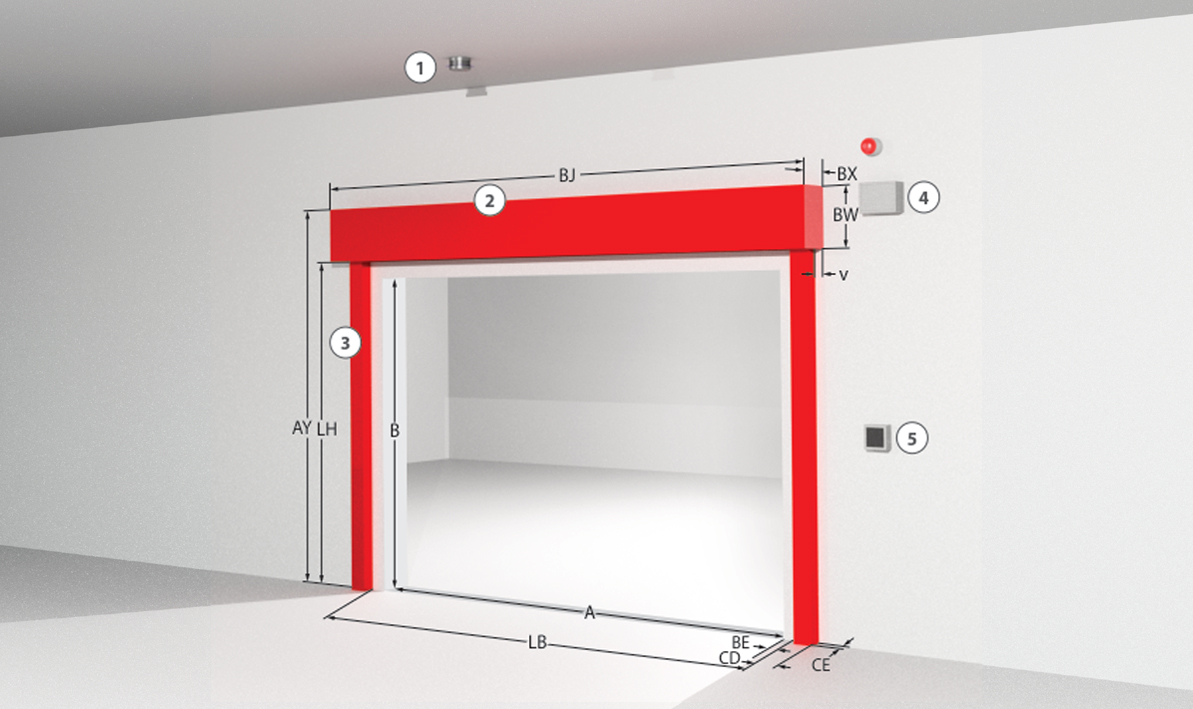
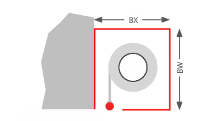
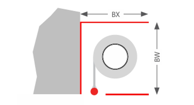
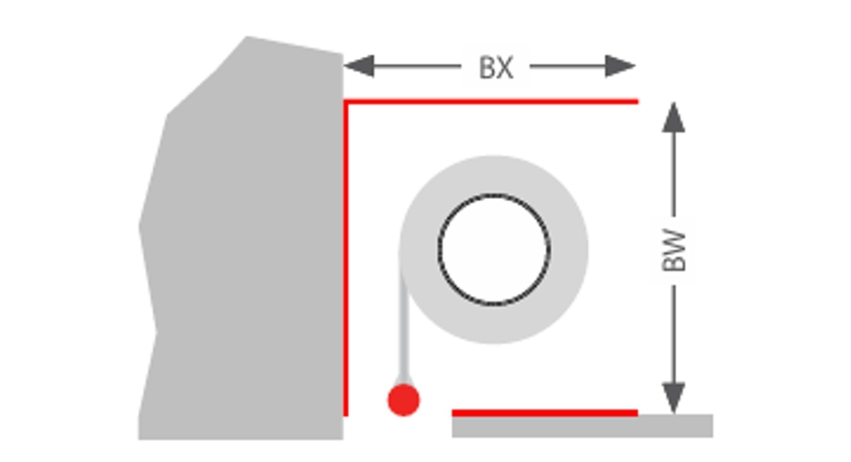
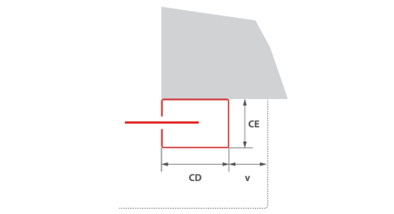
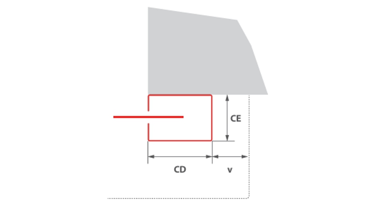
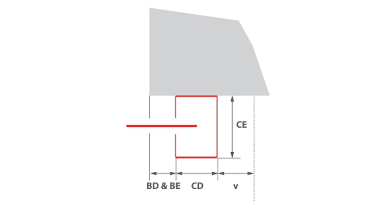
Constructive system design (system drawing)
The combination of classifications or the ratio of clear system width to clear system height may reduce the stated maximum dimensions and the dimensions of the housing and guide rails may vary. The specifications on the quotation apply.
| Classification | Size** [y x r] in mm | Fabric | Wall thickness* in mm | Housing | Guide rail [a(+c) x b] |
| EI1 30/EI2 30 | 7315 x 3800 | Stratex 2 | 150 | Type A | Type 1 oder Type 3*** |
| EI1 60 | 6600 x 4840 | Stratex 12 | 150 | Type B | Type 2 |
| EI2 60 | 4400 x 4300 | Stratex 6 | 150 | Type A | Type 1 oder Type 3*** |
| EI2 60 | 4400 x 4400 | Stratex 6 | 150 | Type B | Type 1 oder Type 3*** |
| EI2 60 | 6600 x 4840 | Stratex 9 | 150 | Type B | Type 1 |
| EI1 90 | 6000 x 4400 | Stratex 12 | 150 | Type B | Type 2 |
| EI2 90 | 6000 x 4400 | Stratex 9 | 150 | Type B | Type 1 |
| EI2 120 | 6600 x 4840 | Stratex 12 | 175 | Type B | Type 2 |
* The installation situation must comply with the building code requirements of the country of installation. The fire resistance of a ceiling or wall support structure and the adjacent components must at least correspond to that of the fire and/or smoke protection closure, fire and/or smoke protection curtain. Evidence of the stability and serviceability of the adjacent walls and structural components must be provided under general ambient conditions and in the event of fire. See also notes on the standard supporting structure in EN1366-7:2004 and EN1363-1:2020. The fire protection system must not be subjected to any additional loads other than its own weight, even in the event of fire.
** larger dimensions on request
*** Type 3 guide rails – maximum size 3000 x 2870 mm