• EN
  • Solutions
    • Fire protection curtains

      Fire protection curtains

      In case of fire, fire protection curtains close wall and ceiling openings. Their construction (roll-down or folding technique) and the use of different fabrics provide for a wide range of applications as well as different protection goals, classifications and time classes. The casing and guide rails of the highly flexible systems blend almost invisibly into the building and allow plenty of scope for sophisticated architecture and open room concepts.

    • Conveyor system closures

      Conveyor system closures

      Various production and logistics processes call for the most diverse types of conveyor systems. If these conveyor lines pass through fire-retardant or fire-resistant walls or ceilings, the openings required for this purpose must be provided with fire protection closures to prevent the spread of fire through the conveyor system or the goods conveyed. In the event of fire, conveyor system closures (CSC for short) must close these openings immediately and automatically. Fire resistance classified according to DIN EN 13501-2 is just as important as the smooth clearance of the closing areas in the event of a fire.

    • Smoke curtains

      Smoke curtains

      A smoke apron is a part of a smoke control system which also includes other components such as natural smoke and heat exhaust ventilators (EN 12101-2) and mechanical smoke and heat exhaust ventilators (EN 12101-3). Smoke aprons restrict the movement of combustion gases within a building in case of fire.

    • Smoke protection curtains

      Smoke protection curtains

      Once closed, smoke protection curtains (SPC) restrict the passage of smoke during the phase of fire formation, so that in the event of a fire, there is enough time to rescue people and animals from the room behind the curtain and to recover material assets without the need for respiratory equipment.

    • Tube sealings

      Tube sealings

      The solution for issues with fire protection dampers in ventilation and air conditioning systems in conveyor processes. Stöbich offers fire protection for pneumatic conveyor lines the closing elements of which are not exposed to the flow of conveyed material. This way, the closing element cannot be damaged or contaminated by abrasive conveyed goods.

    • Control units

      Control units

      Each automatic fire protection system needs a control unit. They are critical to safety, because a failure of this function means that the entire investment into a fire protection sealing has been in vain. Control units coordinate both fire detection and interaction with other control units, such as higher-level building control systems or clearing of the closing area of conveyor system closures.

  • Theme worlds
  • News
  • Contact
  • STÖBICH Brandschutz: Austria Contact

SYSTEM: FIBERSHIELD® | MODEL: FIBERSHIELD®-I

(Kopie 1)

  • Fibershield-I

Product description

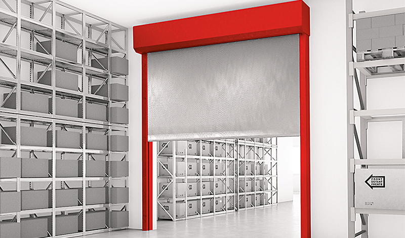
Heat-insulating fire protection closure with a textile design that closes automatically in the event of an alarm, vertical installation position and closing direction.

TypeHeat-insulating fire protection closure with textile design
VerificationCE marking according to EN 16034:2014 in conjunction with EN 13241:2003+A2:2016
Closing directionFrom top to bottom
Fire resistanceEI1 30 – EI2 120 | Tested according to EN 1634-1:2014-03 | Classified according to EN 13501-2:2016
Smoke protectionSa: for joint length 14.5 m for EI1 30 – EI2 120 | Tested according to EN 1634-3:2005-01 in connection with EN 1363-1:2012-10 | Classified according to EN 13501-2:2016
Closing cyclesC0, C1, C2 | Tested according to EN 12605:2000-08 | Classified according to EN 13501-2:2016
Fire behaviour of textileB-s1, d0; E-d2 | Tested according to ISO 11925-2 and EN 13823 | Classified according to EN 13501-1:2018
Environmental conditionsSpecial environmental conditions are not taken into account (e.g. humidity > 80 %, ambient temperature < 5 °C and > 45 °C, wind loads etc.).
Visible surfacesgalvanized | RAL, smooth, silk gloss, standard coour shade | Stainless steel type I V2A material A-1.4301 (bright) | Stainless steel type I V2A material A-1.4301, K240 (ground) | in each case for the visible surfaces of the housing and the guide rails
FiberShield-I Stöbich

Key: System components:
1 = Smoke detector
2 = Housing
3 = Guide rail
4 = Control module
5 = Release device (see the valid general type approval of the brake system for design details of the electrical components.)

Key: Dimensions
Structure
B = Clear shell construction height
A = Clear shell construction width
System
AY = System height
LH = Clear system height
LB = Clear system width
BJ = System width
Housing
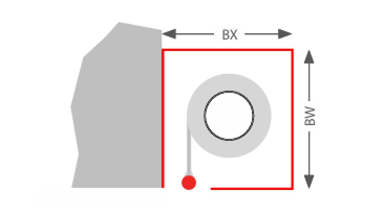
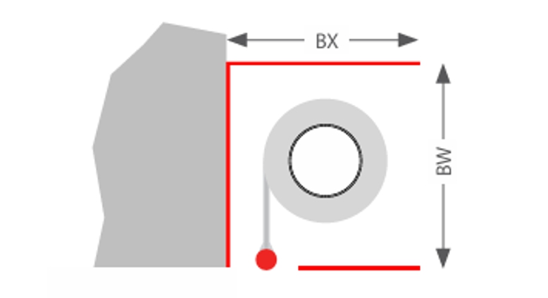
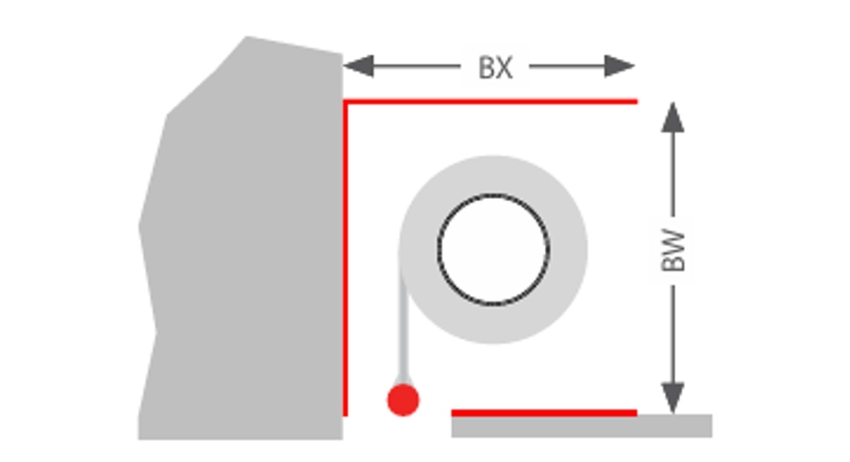
BX = Depth
BW = Height
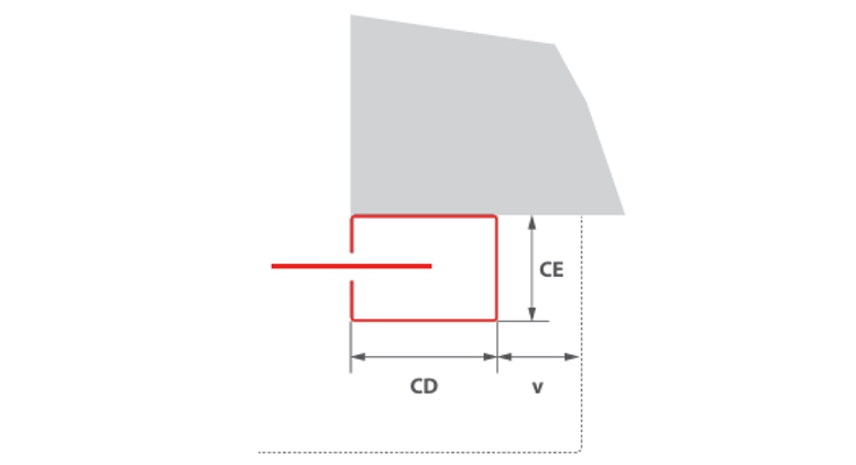
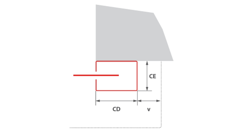
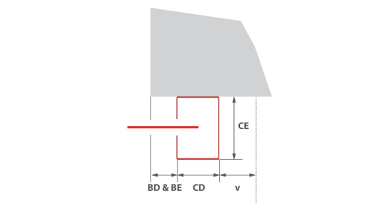
v = Offset between housing and guide rail
Guide rail
CD = Width
CE = Depth
BD = Offset left
BE = Offset right

Dimensions and system design

The combination of classifications or the ratio of clear system width to clear system height may reduce the stated maximum dimensions and the dimensions of the housing and guide rails may vary. The specifications on the quotation apply.

Fire resistance/classificationsSize max.* [y x r] in mmFabricWall thickness* in mmHousingGuide rails
EI1 30/EI2 307315 x 3800Stratex 3150Typ ATyp 1 oder Typ 3***
EI1 30/EI2 307315 x 4950Stratex 3150Typ BTyp 1 oder Typ 3***
EI1 606600 x 4840Stratex 12150Typ BTyp 2
EI2 604400 x 3400Stratex 6150Typ ATyp 1 or Typ 3***
EI2 604400 x 4400Stratex 6150Typ BTyp 1 or Typ 3***
EI2 606000 x 4840Stratex 9150Typ BTyp 1
EI1 906000 x 4400Stratex 12150Typ BTyp 2
EI2 906000 x 4400Stratex 9150Typ BTyp 1
EI2 1206000 x 4840Stratex 12175Typ BTyp 2
SaSa = Joint length must not exceed 14.5 m (standardised: 3-sided without end strip)
C7315 x 4950Stratex 3, EI1 30/EI2 30
C14400 x 4400Stratex 6, EI1 60
6000 x 4400Stratex 9, EI2 60
6000 x 4400Stratex 9, EI2 90
C26600 x 4840Stratex 3, EI1 30/EI230
6600 x 4400Stratex 12, EI1 60/EI260
6600 x 4400Stratex 12, EI1 90

The installation situation must comply with the building code requirements of the country of installation. The fire resistance of a ceiling or wall support structure and the adjacent components must at least correspond to that of the fire and/or smoke protection closure/fire and/or smoke protection curtain. Proof of the stability and serviceability of the adjacent walls and components must be provided under general ambient conditions and in the event of fire. See also notes on the standard supporting structure in EN1366-7:2004 or EN1363-1:2020. The fire protection system must not be subjected to any additional loads other than its own weight, even in the event of fire.
* Deviations from size dimensions on request
** tested wall types according to the installation instructions
*** Guide rails type 3 maximum size 3000 x 2870 mm and no permanent functions C1 & C2

Housing


Wall with housing cover
Type A: BX = 380 mm, BW = 350 mm
Type B: BX = 460 mm, BW = 430 mm
Wall without housing cover
Type A: BX = 380 mm, BW = 350 mm
Type B: BX = 460 mm, BW = 430 mm
Wall without housing cover, with false ceiling
Type A: BX = 380 mm, BW = 350 mm
Type B: BX = 460 mm, BW = 430 mm

Guide rails


Type 1
Type 1
CD = 200 mm
CE = 82 mm
v = 47 mm
Type 2
Type 2
CD = 230 mm
CE = 110 mm
v = 42 mm
Type 3
Type 3
CD = 90 mm
CE = 120 mm
v = 77 mm

BD & BE = 0 mm für EI12 30
BD & BE = 60 mm für EI2 60